We have just completed a quick guide on how to setup and configure your 3 axis brushless gimbal controller, including connection, and also basic software configuration.
Its important to not connect the motors without battery power, as the USB port does not provide enough power and this could damage your board!
During the first setup and configuration please only connect the IMU and USB, not the motors! Once you have done the initial setup, then you should connect the motors and battery before connecting the USB cable.
Connecting the IMU’s and extension board
There are several hardware designes of the alexmos brushless gimbal controller, the images below show you how to connect the various boards. Some of the newer 32bit boards are very easy to connect as you just need to plug in the IMU’s as shown below. These boards include a frame IMU and a camera IMU to improve the stabilisation performance compared to single IMU gimbals.
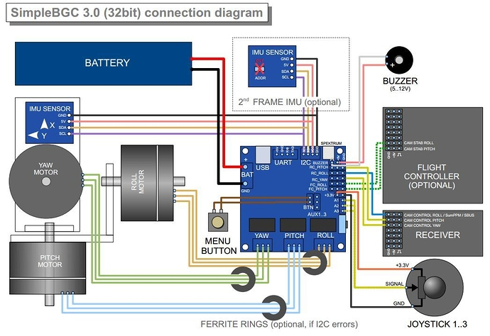
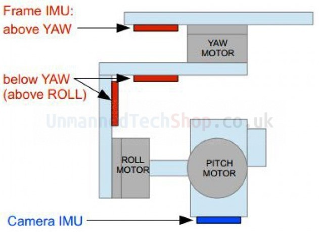
In terms of mounting the frame IMU and camera IMU you can refer to the image below. The frame IMU is the IMU that has two 4pin wires/connections on it. The camera IMU only has a single 4 wire cable coming out of it. The camera IMU mounts onto the camera mount plate, and the frame IMU needs to be mounted above the yaw motor. Please note that only the 32bit alexmos boards use two IMU sensors.
Older Gimbal Controller Boards
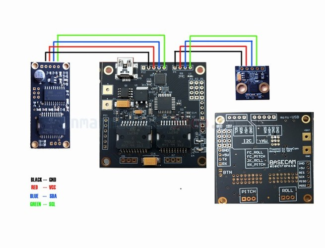
Our older gimbal controller boards required you to mount the Yaw axis board directly ontop of the main board as shown below
If you are using one of the older yaw extension boards, the connection diagram is below
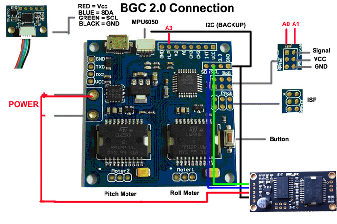
Connecting unofficial alexmos gimbal controllers
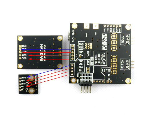
If you are not using the official kit sold by us (or another version of the board) the diagram below will show you how to connect everything together.
Solder the battery connector
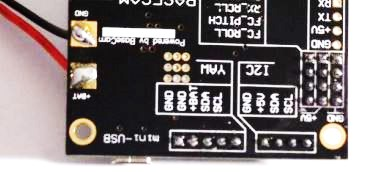
Most of the gimbal controllers you buy today include a battery connector. If its not included in the kit, but you can buy one here. You dont need to use the JST type connector, choose whatever type of connector is the same as the connector on your battery. Please look at the back of the board to indicate which terminal is positive and negative. You will see some small writing showing +Bat (positive red wire goes here) and GND (black ground wire goes here)
Download the configuration software
You will first need to download the latest 32bit SimpleBGC software from here - Downloads : BaseCam Electronics
- You will need to download the SimpleBGC_GUI zip file which contains the software to configure and update the firmware on the board
- You will posibly also need to download the SimpleBGC.hex file which is the firmware that runs on the board if you need to update the firmware to the latest version.
- You can also find a PDF file for each version which has some useful information.
Download the Drivers
If using Windows you might find that it will automatically install the drivers for you, but if not, you can always download the USB driver here -
Silicon Labs
Updating Firmware
If you connect to your board via the GUI and get a board mismatch error, then you will need to either download the correct version of your GUI. Dont try to use one of the other firmware update tools like Xloader/AVRdude unless you know what you are doing, as it could corrupt the firmware/bootloader. Please make sure to disconnect the motors/battery before trying to update the firmware.

Or the best option is to download the latest version of the GUI and firmware and update your boards firmware via the GUI. To do this download the latest firmware.hex file and the latest GUI tool. Open the latest SimpleBGC GUI tool and go to the firmware upgrade tab as shown below. Browse for the latest firmware.hex file and click on the FLASH button.
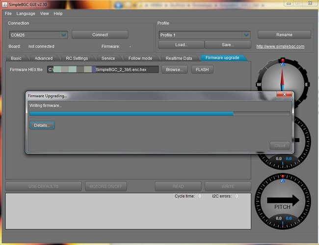
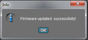
Once complete you will get the message below and you can now connect and configure your board.
Eagle Eye Parameter File
If you are using our Eagle Eye 5D gimbal, or a similar sized 3 axis gimbal for DSLR cameras, then you might find that the parameter file will help you get stared with tuning. There are also different profiles for use with a joystick etc…
Calibrate Accelerometers
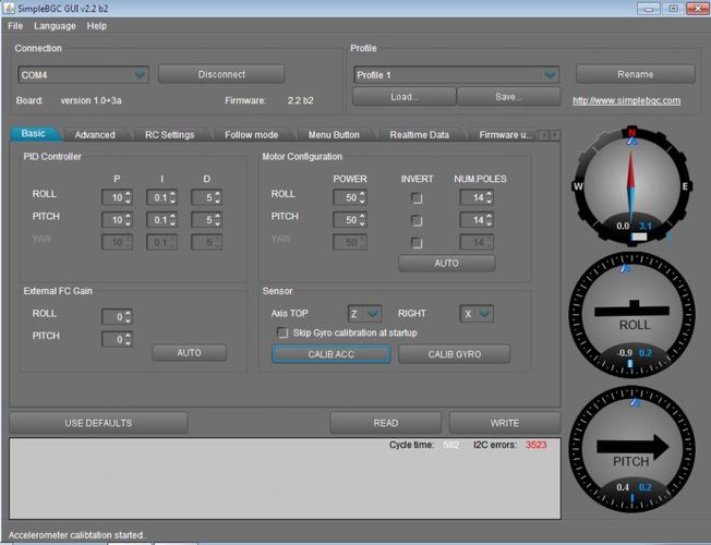
With the IMU on a perfectly level surface, you can start the calibration process, as this is best to to whenever you update the firmware.
Enable Yaw axis extension board
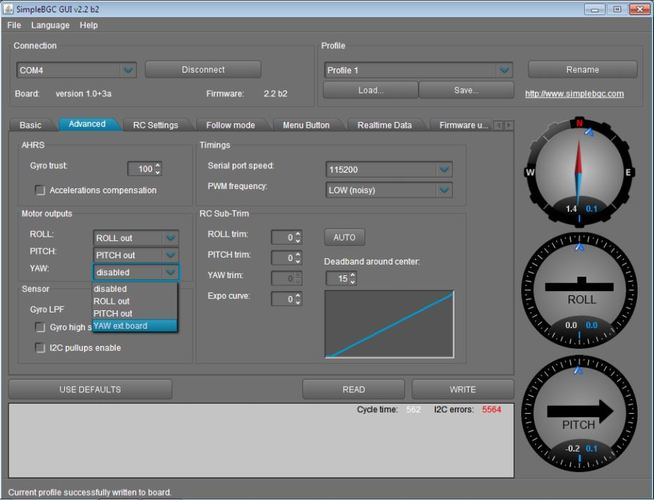
Change other settings
-
If you motors are noisy, then you should change the PWM frequency to
High (advanced tab) -
You will need to complete the motor configuration page (best to start by trying the auto config (click auto button), also set the number of poles according to the motors you are using.
-
If you are getting lots of I2C errors please ensure your board has enough power connected to it (dont only power it via USB)
-
Adjust PID values, this is abit tricky and I will probably release a separate guide on this later.
I am gettings lots of I2C errors
If you are gettings lots of I2C errors with your brushless gimbal controller here are some tips
- Sensor cable cannot be longer than 40 cm
- Motor interference cause i2c error. More power, more error. Make sure your sensor cable is not close to the motors too
- Ferrite rings can help reduce I2C errors
- For best performance make sure the voltage is between 10.8v~11.3v (3 cell Lipo battery) Many users have reported an increase in I2C errors when powering the board via USB only, and also with a 4 cell lipo battery.
Yaw Extension board is not working, (lots of i2c errors)
If the 2 axis alexmos board works fine, but as soon as you connect the Yaw axis extension board, nothing seems to work (you get lots of i2c errors, or a message saying that the sensor is not connected) then this is most likely due the the fact that the board does not have enough power. Most users find this error when they are testing the board under USB power only.
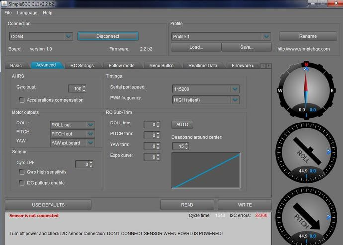
To resolve this error simply make sure that you connect up the battery while setting up the Yaw extension board and once you enable the YAW extension board it should all work fine. This is mainly to to the shared i2c bus between the Yaw Extension board and the IMU not having enough power under USB only.
Balance your gimbal
Its also very important to properly balance your gimbal, you can find out some more information in the topic below.
Connecting the motors
As for the motor connections, it does not matter which order you connect the 3 wires in, just make everything consistent. (and make the middle wire from motor go to the middle pin on the board).
Will add some more information here with photos at some point
Using the Alexmos Auto Tune function
With the newever version of simpleGBC firmware you have the ability to run the autotune function which will find the optimum PID settings for each of the 3 axis on your gimbal which is great for new users who have not setup PID gains before. Here is a great video giving an overview of the process:
Adding a Joystick
Adding a joystick is useful if you are using a handheld gimbal as it lets you control the pitch/roll angles with your thumb as you are holding the gimbal. Details on what you need and how to connect it are shown in the topic below.
Adding Bluetooth
If you want to be able to change the settings remotely via an android app on your phone/tablet then you can connect a Bluetooth module to your board. You can see how to do that on the topic below.
What battery should I use?
If you are using your gimbal controller on your multirotor drone then its best to power your gimbal and controller with your main flight battery. If using a handheld brushless gimbal, the size of your battery will ultimately be based on the desired weight and operating time you need. Typicaly I prefer to use a 2200mah 3S Lipo battery as it gives about 1-2 hours of operation and is very light. When it gets flat it only takes a few seconds to change it to another one. If you use a larger battery your gimbal will work longer between charges, but it will be much heavier to carry and use.


 . But now everything is fine. Roll and pitch is perfect. But wen i try to tune yaw suddenly the controller starts beeping and emegency stops appears. Everytime.