I recently built an Arducopter Y6 using the Pixhawk autopilot with a tarot T-2D gimbal kit and I wanted to connect a video transmitter and OSD to my copter. I thought I would create this small guide on to how to do this and some of the problems that I encountered.
Step 1: Connect the Minim OSD board to the Pixhawk
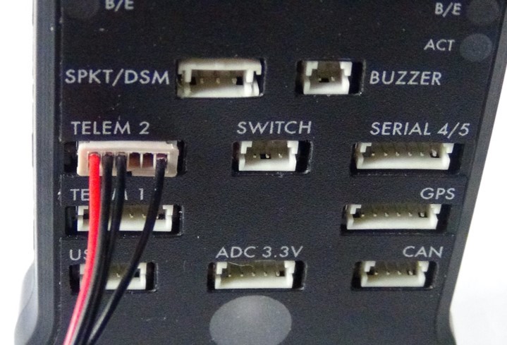
As it says in the heading, I found that a good starting point was to connect the OSD board to the previously installed Pixhawk. You first take the Minim OSD cable and connect it to the board. There is one red wire among the black ones and so it is easiest to reference via this wire. This red wire connects to the port that is labelled +5v as can be seen in the picture below.
You then need to connect the other end of this cable to the Pixhawk. This is easily done but you need to make sure to connect it to the ‘TELEM 2’ port as shown.
Step 2: Connect the gimbal to the OSD board
Now we need to connect the tarot GoPro FPV cable to the OSD board. This FPV cable was included with the tarot T-2D gimbal kit. There are two connectors at the end of this tarot cable, and you need to ensure that you connect the right one in the right place. The picture below displays this cable and here we are interested in the video line end.
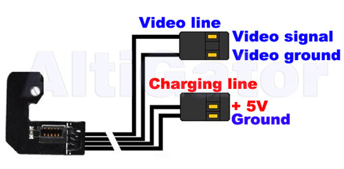
It is important that the ‘video signal’ and the ‘video ground’ cables connect to the right pins in the OSD board. Using the orientation of the video line connector seen in the picture above, be sure to attach this connector to the upper level of pins when the board is upright. This is illustrated in the photos below.
If you have done this correctly, then the ‘video signal’ cable should be connected to the ‘VOUT/VIN’ pin and the ‘video ground’ cable should be connected to the ‘GND’ pin, as shown below.
Step 3: Connect the video transmitter to the OSD board
So, at this stage we have the gimbal connected to the OSD board, and the OSD board connected to the Pixhawk. We now need to connect the video transmitter to the OSD board.
The illustration on the back of the transmitter box is very useful at this stage as this shows which cables you should use. In the box with the transmitter, you receive a bunch of different coloured cables and here you choose the yellow and the black cable. The yellow is the ‘video input’ and the black is the ‘ground cable’.
Following the diagram on the back of the box, the yellow wire plugs into the 3rd port in the transmitter, and the black into the 5th. You then need to connect these wires to the OSD board as follows. As the tarot cable connector is connected to one set of pins already, you know which set of pins the yellow and black cables should attach to. The photo below shows what you should end up with.
Step 4: Connecting the video transmitter to the power source
Within the video transmitter box, you of course get the power cable for the transmitter, which is the cable with the red and black wires. Initially, I thought I would solder this cable directly to the power distribution board on the copter to power the transmitter. However, due to number of devices that this board is powering, interference of the video feed would be more than likely and so I decided to use a Fatshark power filter. This has the advantage that it filters out any interference, and it also requires no soldering.
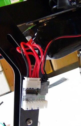
Powering the transmitter now consists of plugging the Fatshark filter into the battery, and then plugging the filter cable into the video transmitter. However, you must be careful here with the positive and negative orientation of the wires in the filter compared with the power cable that you receive with the transmitter. Rather annoyingly, they are positioned differently to one other, as shown below.
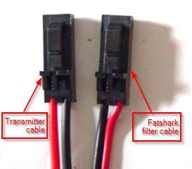
Here, you can see positive power input (the red wire) on the transmitter cable is on the left, where as the corresponding cable on the Fatshark cable is on the right. This means that if we plugged the filter cable into the video transmitter as it is here, there is a danger of damage to the transmitter so this is best avoided.
This means that you must swap the two cables in the filter cable around so that when it is connected to the transmitter, the positive input and the negative input are connected to the right ports. This process is fairly simple, and the general principle is shown in this video: https://www.youtube.com/watch?v=Pz8yAdv815U. (Excuse the soundtrack…)
Once this is done, you can plug the filter into the transmitter, and plug the filter into the battery, and the video transmitter will be powered. Make sure to attach the filter somewhere near the battery pack (I attached it to the leg nearest the battery as shown below).
Step 5: Finishing up
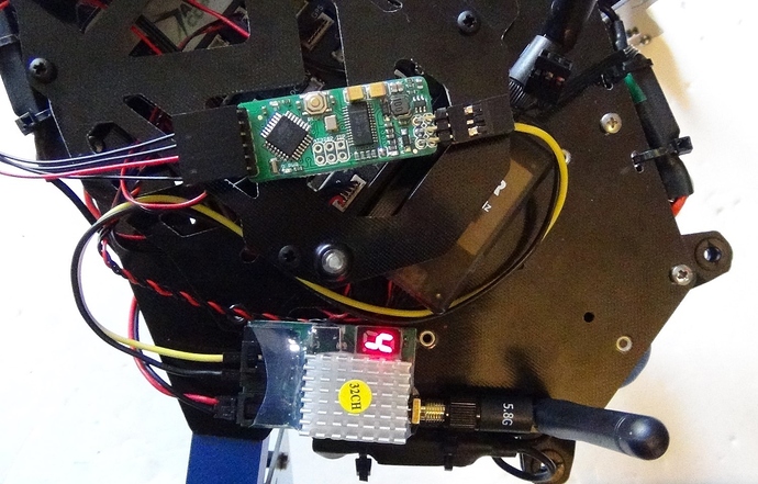
And there we have it; all wires and cables connected and everything powered. All that’s left to do now is to attach all of these components to your copter anywhere where you think is appropriate. This is my finished product:
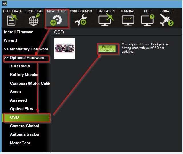
Note: If you do not receive any data onto your OSD board, you may need to enable it on Pixhawk. You do this via Mission Planner following the steps highlighted below
Equipment Used (all found at unmannedtechshop.co.uk)
- ArduPilot Mega Minim OSD v1.2
- Minim OSD cable
- 5.8Ghz 400mw FPV Transmitter (32 Channel)
- Filtered Balance Lead Power Supply
Thanks for reading and if you have any questions, please let me know and I’ll try and answer them.
