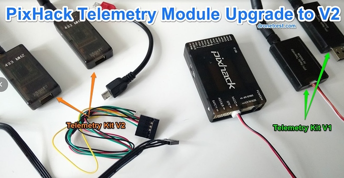
By default we currently sell our pixhack kit with the 433mhz telelemetry kit V1. However since the release of the pixhack we have now released an updated version of the unmanned telemetry kit which main feature includes a USB connector along with a 6 pin DF13 connector. So if you already have a pixhack kit and would like to start using the new telemetry kit modules then here is a quick guide on how to swap the connectors.
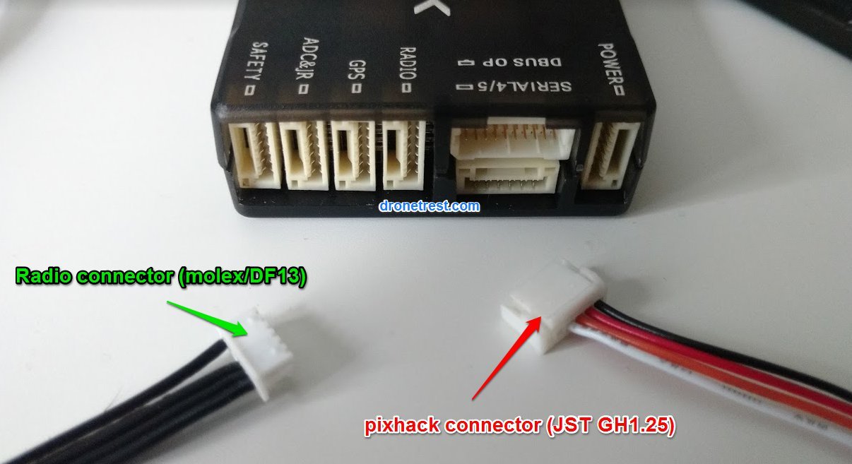
The V1 telemetry radio is connected to the pixhack via the included cable, but the 4pin connector is not compatible with the 6 pin connector on the v2 telemetry module.
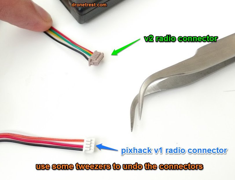
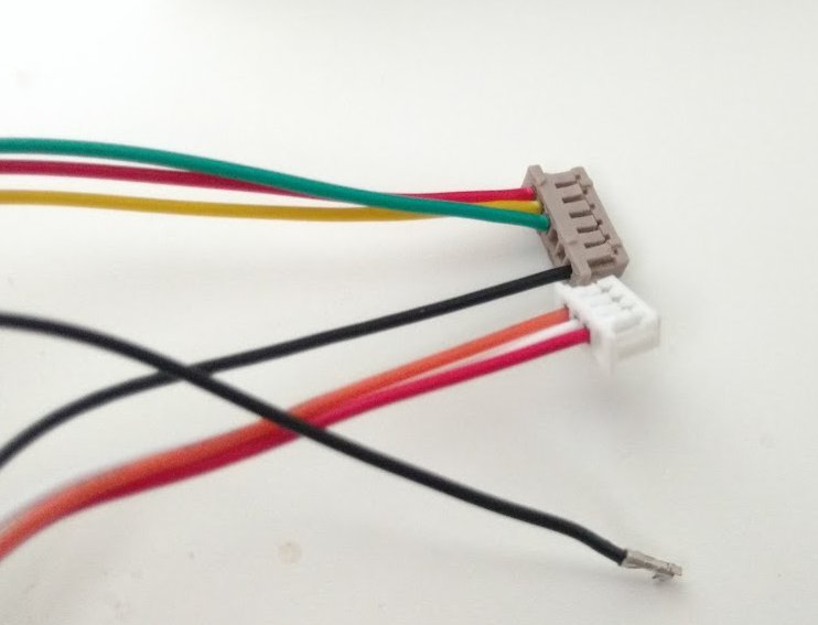
Fortunately the DF13/1.25mm Molex connectors on the two radios are directly compatible so its just a matter of unclipping them from the plastic connectors. This can be done using some tweezers, but if you are not sure how to do this please check out this video no changing molex connectors. Just be careful to not snap any of the plastic clips.
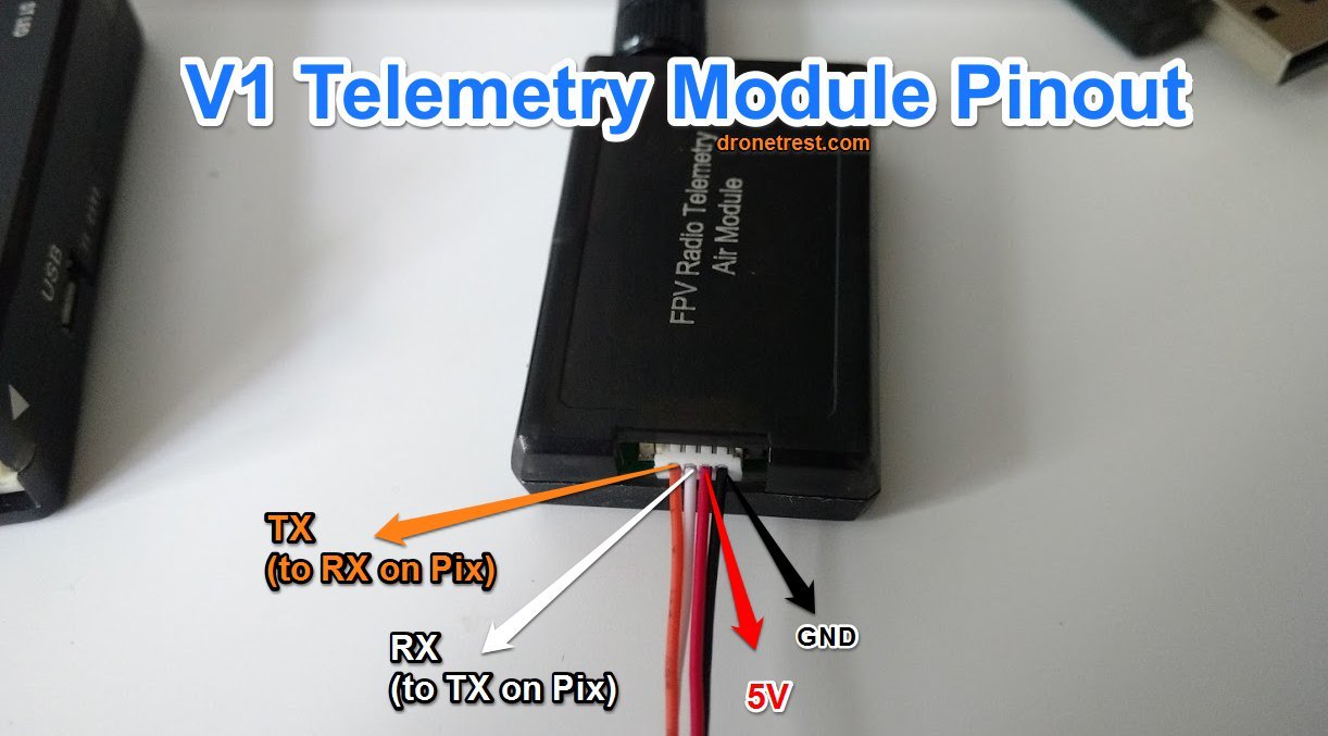
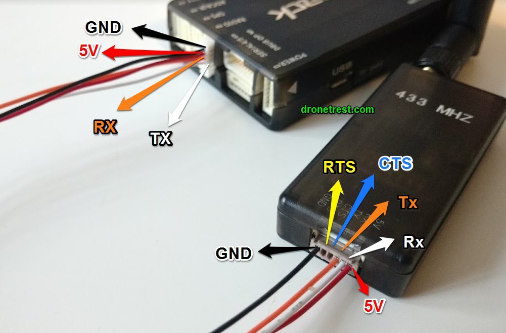
Once the wires are swapped according to the diagram below you will be able to plug everythign together and you are good to go using your new V2 telemetry modules with your Pixhack. Although not technicaly required, you will get better peformance with your radio if you also connect the CTS and RTS pins between the radio and your pixhack. We will soon sell a 6 pin cable to easily use these connectors when we upgrade the pixhack kit.
As shown in the image above, the TX from pixhack goes to the RX port on the telemetry module. Similarly, the TX from the telemetry module goes to the RX on the Pixhack. For more details check out our pixhack quickstart guide for the pin mappings on the pixhack.
As usual if you have any questions please let me know and I will do my best to try to help ![]()
 Is it recommended to upgrade? what is the difference?