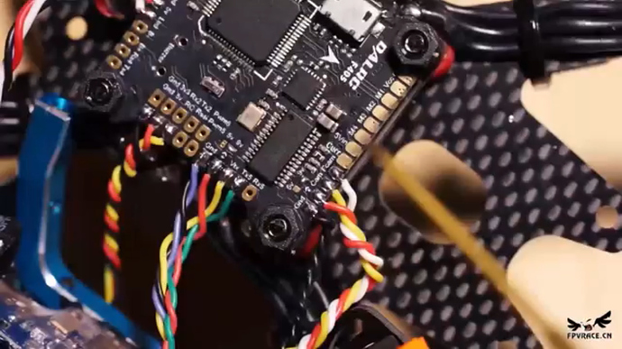
I am using this 4in1 ESC
And this fc-
The wiring is really puzzling for me.
I figured out wiring with the motor and ground wires but where do I solder other wires?
Also the fc has a solder pad for vcc, curr and another pad between m4 and curr.
What are all these pads for and what wires do I solder onto them?
Can you get a good picture of the top of the FC… the online ones are poor and I can read the silk screen very well.
Can you get a picture of the ESC with the Cable plugged in as well. So we can see the wire color order.
That should give us enough information to tell what color needs to go where
@RobinSingh
Hi,
This image should help with the ESC
Cheers
Steve 
Is this fine?Seen it from a youtube video
I can’t say for sure, but seems correct. Basically you need to make sure that motor output 1 from your FC goes to in 1 on your ESC, and the same for 2-4 according to the diagram @stevietee10 kindly provided.
Then the vbat from ESC, goes to the vbat pin on your FC (so your FC knows your battery voltage) and the crnt output form ESC goes to current sensor input on your FC.
Since that ESC does not have a 5v bec, you will need to power your FC some other way. It should have this info with the dalrc FC manual
So this is what I got-
Crnt-curr
Vbat-?(probably vcc)
Hi Robin @RobinSingh
The item listing on the Banggod site has a reasonably good wiring diagram covering most connections.
The problem is you have to scroll way down to find it and it’s not easy to reproduce as a document with any real clarity. Referencing it on screen should be workable though
Cheers
Steve 
Hi Robin @RobinSingh
Just found these… the wiring diagram is very clear BUT you will need to download it to get full file size/resolution
Cheers
Steve 

